LPKF Mill
- Former user (Deleted)
- Bradash, Mihailo Rayko
- Former user (Deleted)
- Wirth, Justin C

Refer to the Material and Process Compatibility page for information on materials compatible with this tool.
Equipment Status: Set as UP, PROBLEM, or DOWN, and report the issue date (MM/DD) and a brief description. Italicized fields will be filled in by BNC Staff in response to issues. See Problem Reporting Guide for more info.
| Status | UP |
| Issue Date and Description | |
| Estimated Fix Date and Comment | |
| Responding Staff |
iLab Name: LPKF Mill
iLab Kiosk: BRK Packaging and Assembly Core
FIC: Dimitrios Peroulis
Owner: Mihailo Bradash
Location: BRK 2254 - Galley
Maximum Wafer Size:
Overview
General Description
Maximum material Size: 200 X 260 X 10mm
Maximum PCB Platable Size: 200 X 260 mm (for reference if through hole plating will be required)
Please Read this Before Requesting Training on this Tool
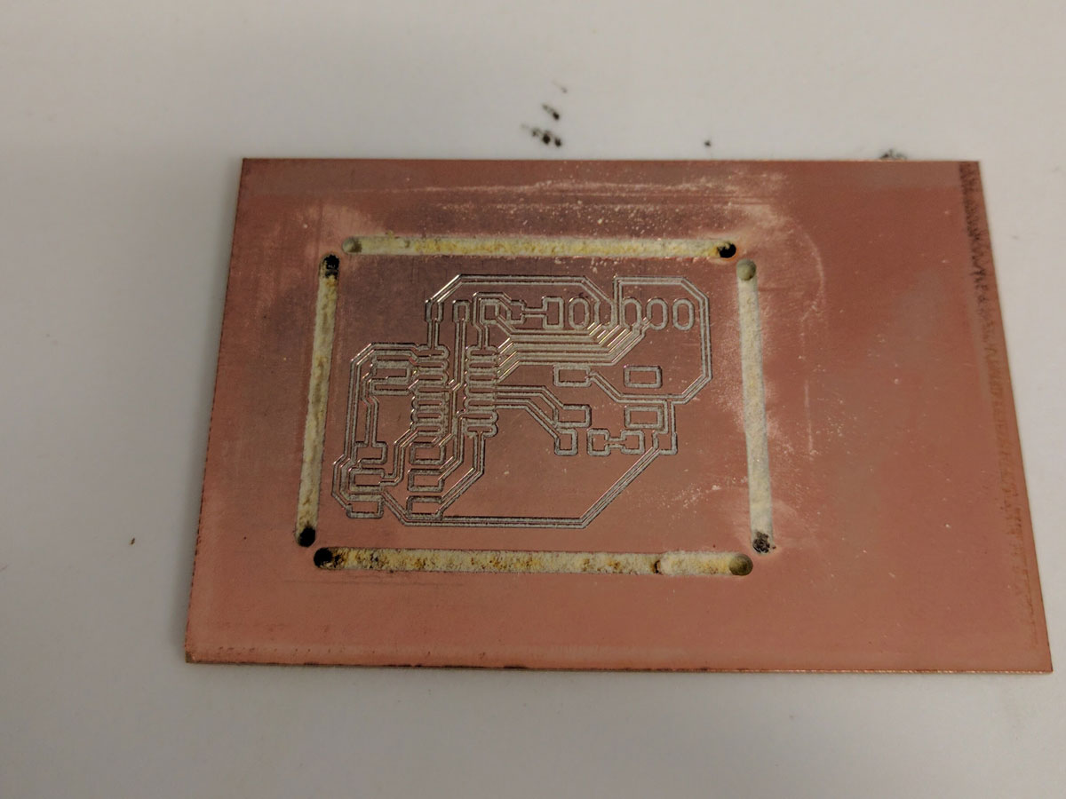
Notice 1:This tool produces bare copper boards and limited 3D milling. The image to the right is an example board produced by an |
|
Notice 2: Birck does not provide cutting tools to operate this tool. Before you can be trained on this tool, you will need Page 7 - Part Number 129103-1 - Starter Package - $450 (2020 pricing) See catalog link to the right for details and pricing options. | |
Notice 3: Due to Prior issues with the LPKF mill, and extensive updates to the tool. Birck has decided to move this tool to a "selective approval" use case. The goal is to have that user on the tool frequently so they become, and maintain, proficiency at a level that will reduce potential damage to the tool due to operator errors. |
Ok, so I read that, and I don't think it's a good fit. Now what..?
| A simple google search for prototype PCB fabrication will turn up many options for online short run PCB services. Review their capabilities carefully as they do vary from service to service. Some offer same day turn around! |
Ok, so you still want to use the LPKF. Please continue below for more information!
Specifications
| Description | Value |
|---|---|
| Workplace noise level | ~71 dB (A), without soundproof hood and dust extraction |
| Range of spindle speeds | Up to 10,000 rpm (variable) |
| X and Y feed rate | 150 mm/s |
| Drilling rate | 150 strokes per minute |
| Tool Change | Manual |
| Tool shank | 3.175 mm diameter (0.125 in) |
| Cutting depth adjustment | Automatic |
| Working area | 305 x 229 x 23 mm |
| Resolution(X/Y) | +/- 0.25 um (0.01 mil) |
| Repeatability | +/- 5 um (0.2 mil) |
| Minimum drill diameter | 0.2 mm |
Technology Overview
The modified LPKF milling machine now makes use of a "Duet 3" 3D printer control board and it's respective interface. This along with a revamped z-drive and spindle motor allow for the use of true 3D milling operations as compared to the prior 2D.
Sample Requirements and Preparation
Items that require milling should be prepared as either a Gerber, or IPT/SLDPRT (3D CAD) file type.
Depending on your file type preparation for milling will be different, please see the appropriate sub sections within the "Standard Operating Procedure" section.
Standard Operating Procedure
System start up
- Enable the tool in iLabs and make sure tool has started up and power is switched on.
- Turn on and log-in to the machines PC.
- Check that the switch on the dust extraction unit is set to the manual position.
- From the desktop screen select and open the "LPKF" hyperlink.
- From here you should be within the "Duet Web Controller" on the main "Dashboard" page, and ready to initialize the machine.
- To initialize the machine navigate to the "Home All" button and select, note make sure there is nothing preventing movement of the axis on the machine as this can result in a crash.
- Once machine has been homed navigate to the "Upload and Start" button at the top of the screen, and select.
- Upload your file as detailed by the file types below. If you have any issues with this step and or any following, please stop the machine and contact The responsible engineer for this tool.
Gerber files
3D CAD files